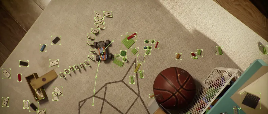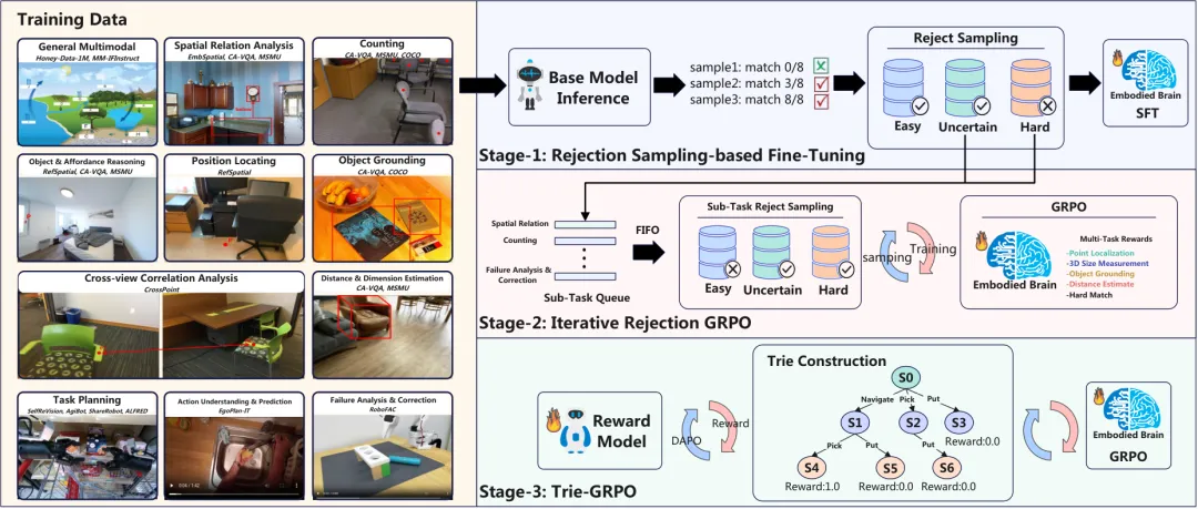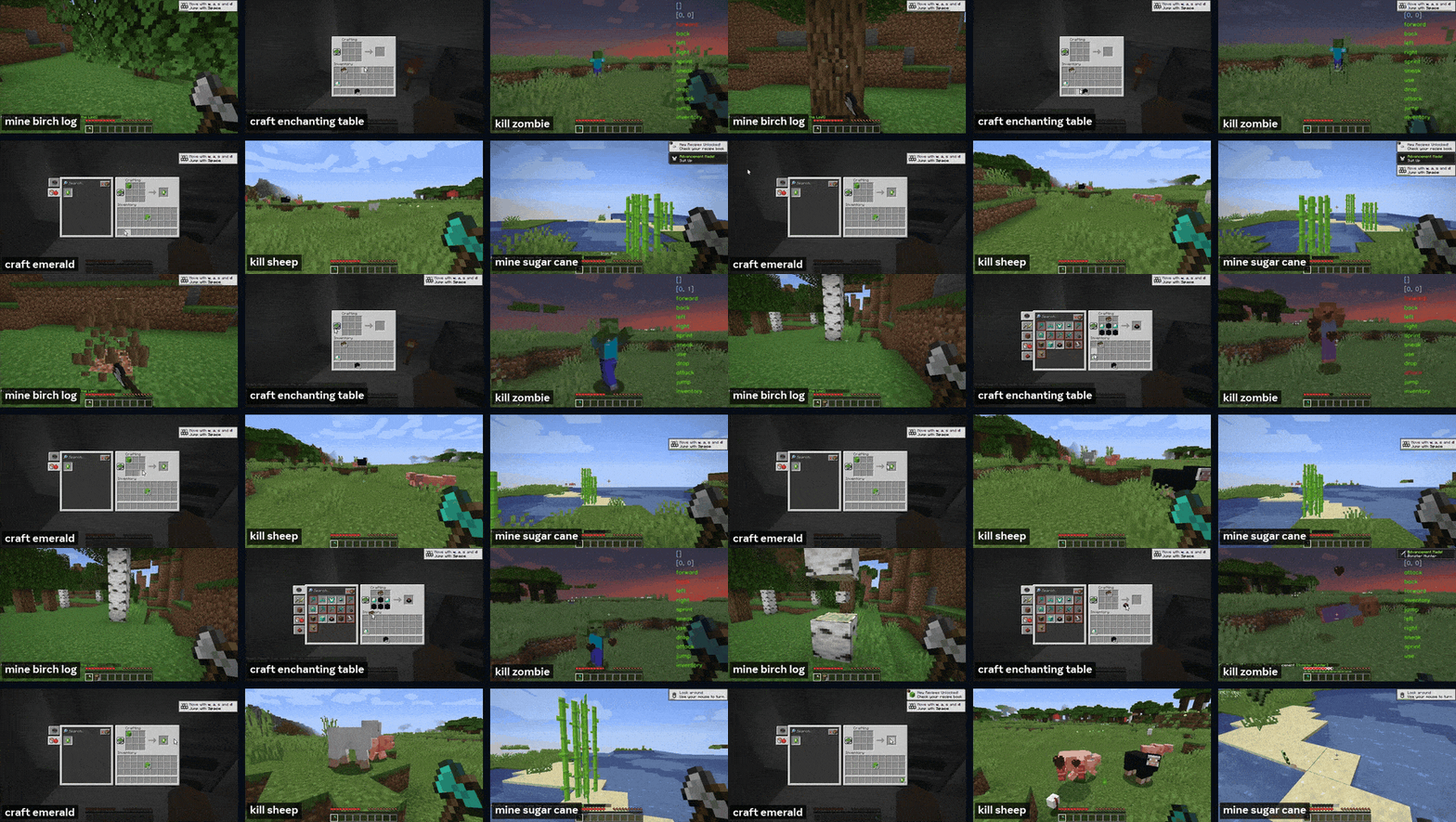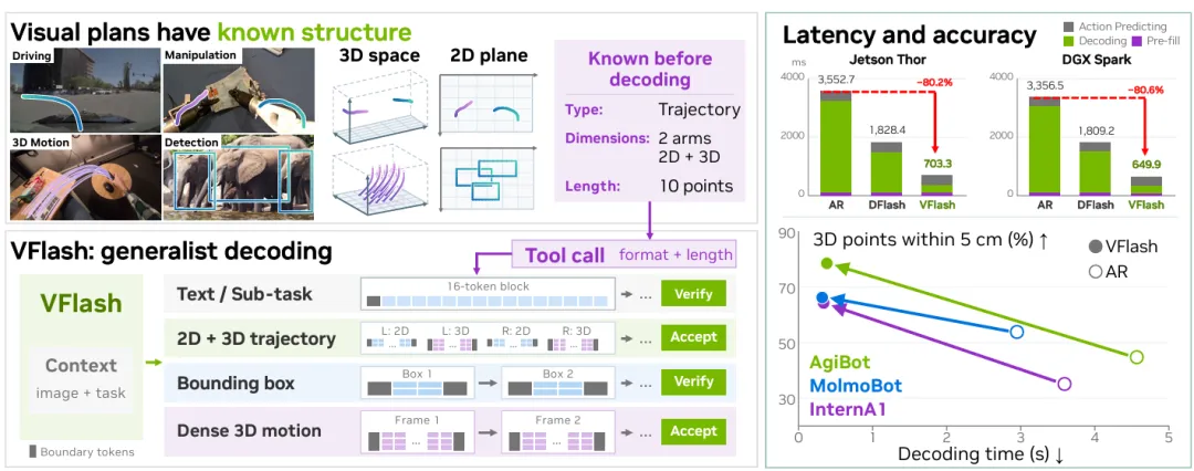
Figure one:VFlash is a general-purpose decoding framework for Physical AI tasks such as robotics and autonomous driving to achieve fast, accurate visual programming. By aligning predictive blocks with known structural components of the visual element, VFlash is able to simultaneously decode common structured outputs, such as boundary frames, modified 2D/3D trajectories, and viscous motion, while retaining the predictive decoding for verifying text and submission plans. VFlash improves the accuracy of 3D robot trajectory programming compared to regressive AR decoding, while significantly reducing decoding delays on NVIDIA platforms, including Jet Thorson, DGX Spark, and H100.
Summary
Models for Physical AI tasks, such as robotics and autonomous driving, do not need to be reasoned solely through language. They can be used to represent spatial targets and predict motion using visual program focal points, boundary frames, and trajectory arcs. However, since the regression of visual language models to coordinate-by-coordinate tokens, geogeneration of these programs has made richer predictions increasingly expensive.
We proposed VFlash, a way to achieve fast, accurate visual planning through Flash Primitive Decoding. VFlash uses the known structure of the visual element to generate the entire element through a lightweight draft model in forward propagation to predict its coordinates together. Its layout is adjusted according to the type, dimension and length of the element, supporting both tight boundary frames and longer change trajectories.
The key is that achieving spatial accuracy does not necessarily require the exact sequence of tokens to be reproduced from the return model. Therefore, VFlash uses labeled tokens to train and directly accept structured effective predictions without the token being consistent with the target model. In the evaluated 2D and 3D robot trajectory tasks, VFlash has always been able to reduce prediction errors compared to the return decoding. Initial single-step rollout measurements show that the generation rate of 3D point movement predictions has increased by about 25 times.
1. Quotations
VLMs are increasingly being used as the superior brains of Physical AI systems: they understand visual observations and mission instructions to guide the behavior of robots and autonomous driving systems. Their reasoning is not necessarily expressed only through language. VLMs can represent intermediate predictions as visual plans: points and boundary frames are used to identify relevant locations or objects, trajectories are used to describe expected movements, or predict how the scene will evolve. Recent work uses spatial trajectories and visual imagery to guide motion generation. These plans express spatial goals and expected movements clearly before performing movements. Each visual element has identifiable boundaries and organized coordinate layouts.
As spatial details become more abundant, efficient production of these programs becomes more important. Longer trajectories, more objects, and combined 2D imaging and 3D forecasting require more coordinate tokens, and since the return VLM must decode these tokens in sequence. For physical intelligences that need to update programs with new observations, sequence decoding limits spatial details and update frequency under fixed delay budgets.
Parallel decoding provides a promising pathway to reduce the cost of this sequential computation, especially for batch size 1 and delay-sensitive Physical AI systems. Existing methods include predictive decoding through parallel verification, and distributed language decoding through parallel noise modeling (dLLM). However, compared to self-reporting models, dLLM typically requires a balance between speed and quality.
In this work, we proposed VFlash: a general decoding framework for Physical AI, as shown in Figure 1. It supports text at the same time, such as submission plans, as well as multiple visual elements, such as boundary frames, changing trajectories, and intensive 3D motion predictions. Our research found an interesting phenomenon: lightweight scattering sketch models not only decode much faster, but even exceed the spatial accuracy of their auto-return target models in visual programs.
The structure of the visual element helps explain this finding: once the type, dimension, and length of the element is specified, its boundaries and coordinate layout are also determined. By aligning draft blocks with these boundaries, it is possible to jointly predict entire geometric objects and decode tens to hundreds of tokens at a time in forward propagation. These observations encourage us to align with the boundaries of the entire element in training and decoding, and to accept directly the structured draft that is effective, without requiring it to be consistent with the target model at the token level; for text, we continue to retain the decoding experience.
At the heart of VFlash is Flash Primitive Decoding (FPD). It trains and reasones on draft models based on requested output structures. The tool calls for specified variable prediction sizes, while the column type determines its coordinate layout. Lightweight spreadsheet draft models are conditioned to freeze target VLM attributes, learn to predict complete diagrams from labelled spatial data. When reasoning, the decoder imposes constraints on the corresponding layout and fully accepts valid diagrams. The target VLM provides context for subsequent predictions, while ordinary text continues to use the prediction decoding validated by the target model.
We evaluated VFlash in 2D and 3D robotic trajectories, boundary frames, and dense 3D point motion predictions, and studied its application in downstream operations and driving tasks. In the evaluated robotic trajectory tasks, VFlash was always able to reduce predictive errors compared to its self-return target model. In the downstream robot operation pipeline shown in Figure 1, VFlash was able to deduce a decrease in delays on both Jetson and DGX Spark. These programs also provided useful conditional information for the action model: on MolmoSpaces, the VFlash-conditioned world action model achieved an average success rate of 70.2% on four missions, whereas the baseline was 62.6% on Thorson and DGX Spark.
In addition to acceleration, our work suggests that parallel decoding may play a broader role in multi-modal systems. Harmless deductive decoding retains the output distribution of the return target model; while for structured visual programming, predictions can be judged based on the predicted spatial accuracy and the practicality of its interactions, which is consistent with the relaxed acceptance of the standard. VFlash enables VLM to program visually in System-1 mode, while simultaneously generating rapidly structured spatial predictions by coordinate decoding.
2. The method
This section introduces VFlash's general-purpose decoding framework for Physical AI, the contents of which cover the preparation knowledge of DFlash, and the detailed design of Flash Primitive Decoding, as shown in Figure 2.
2.1 Preparing knowledge
In the decoding hypothesis, the draft model presents a token, and the target model simultaneously validates the tokens. The average delay for each token is:
Among them, it is the number of tokens expected to be accepted for each cycle. DFlash uses a lightweight block of spreadsheet models to reduce the computational cost of the molecular portion. The characteristics of the target model selected layers are combined and inserted as key and value into each layer of the draft model.
One of them is the cost of generating the draft in token order.
However, longer drafts do not necessarily enlarge: greedy validation is only accepted until the first position is inconsistent with the target model:
It is usually reached at a location much lower than that of hydrogen. Therefore, increasing the length of the block does not necessarily increase the final throughput.
For text generation, the goal is to verify the output distribution of the target model by preserving the target model. However, token level consistency does not necessarily reflect spatial accuracy. VFlash maintains the draft generation architecture and replaces the above verification method with a visual graph that accepts the structure directly.
2.2 Flash Primitive Decoding
Spatial objects such as visual observations and mission instructions, VLM forecasts boundary frames, robot trajectories, or future point locations. Each forecast is a visual graph whose schema specifies the type, dimension, and range of the graph. Thus, the function of each coordinate is fixed, and the specific values still need to be deduced based on input.
2D image coordinates and 3D space coordinates of a trajectory can form a single coordinate and combine predictions. For longitudinal predictions, the tool calls declares its range; this range determines the layout together with the type of the coordinate. For fixed-size predictions such as boundary frames, the layout can only be determined by the type. Thus, the structure is known before the coordinate predictions, and each decoding block covers an entire coordinate.
Schema defines a block of length: an observed initial token followed by a masked token.
In contrast, in the context of a given layout and target model, VFlash predicts all locations in a conditionally independent manner by means of a single forward propagation:
Thus, the complete graph is the basic unit of parallel prediction, and the estimated budget is determined by the request rather than by the fixed window. The same principle applies to target models that output coordinates in normal text form: we align their numerical fields in a fixed-width layout, and then convert the prediction results back to the text format of the target model.
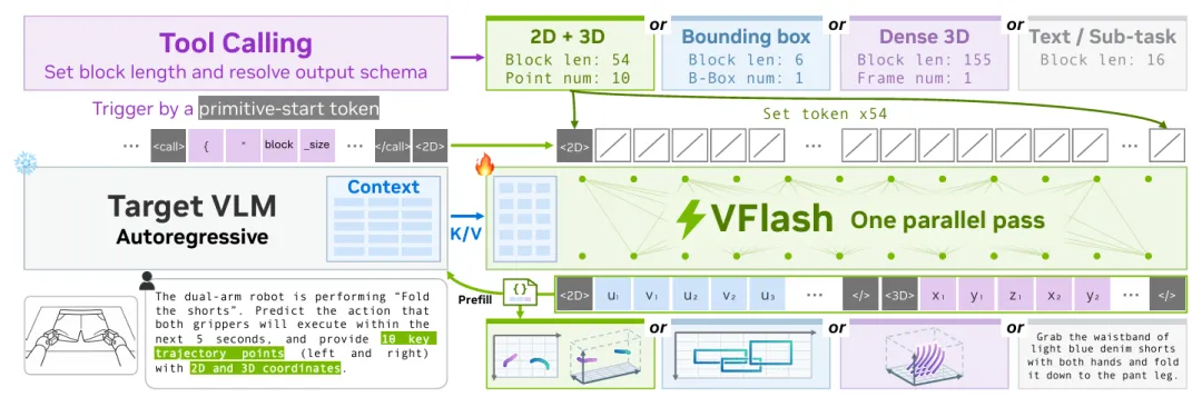
Figure 2: Design of the FPD.The initial token of a token triggers a prediction block, whose layout is decided jointly by the type of the token and the call of the previous tool. By making the prediction block adapt to the structure of each token, VFlash does not need to be consistent with VLM at the token level, which supports different space formats and lengths.
2.3 Token indicates
Visual plans typically require larger and variable-length draft blocks. For example, NAVSIM needs to predict 8 flight points in 4 seconds, and Waymo needs to predict 20 flight points in 5 seconds. Generating these blocks will challenge format compliance and spatial accuracy. We found that two design principles helped address these challenges:
Border alignment determines what content is predicted together.Each draft block covers a complete graph element, avoiding cuts caused by fixed-length windows. The tool calls the length of the declaration block, thus determining the number of flight points. Shared layout templates can accommodate different lengths, allowing the entire graph to be generated in a single forward propagation.
Location alignment determines what each location predicts.Before decoding, the function of each position is known: it may correspond to a flight point, coordinate axis or separator. This supports parallel predictions with a consistent layout and the imposition of step-by-step position constraints when reasoning.
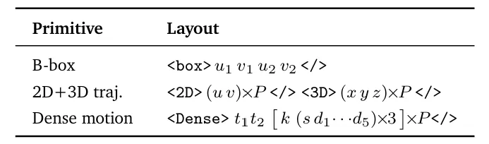
Table 1: The layout of the diagram.Each block starts with the initial token. The number of points represented; and the coordinates represented separately by the image plane coordinates represented by the special token and the coordinates represented in metric units.
To maintain this layout, each coordinate must occupy a fixed number of positions. Recent VLMs have unified the image coordinate to 0×1,000 and written it as plain text; models built around visual elements typically use special tokens. A special coordinate token occupies one position, and the results of text tokenization change the position of the subsequent coordinate with numerical values. VFlash supports both modes of representation.
For our foundation model, the typed token marks the beginning and end token boundaries, as well as the switching between text decoding and decoding. Each coordinate uses one of 1,001 special tokens to limit predictions within its legitimate vocabulary.
For the target model for text tokenization, VFlash assigns one symbol bit and five digital bits to each coordinate, and the unused high bit is filled by a mask token. This fixed-width grid retains the function of the locations and is then converted back to the text format of the target model, whose separators are used to mark block boundaries. Table 1 and Appendix A give the format details.
2.4 Training
We first used next-token supervision to make a self-reporting VLM fit into a spatial response format; then we froze the model and trained a shallow non-causal draft model based on its characteristics. For a labeled block, we minimized the weighted cross-section of formula 3:
All logits are combined in a single forward propagation. The use of uniform weights in the position of the array differs from the decreasing weights in the forward position below the formula 2. The key is that the tag comes from a marked coordinate or transformed grid, rather than the subsequent output of the target model. Therefore, the goal of optimizing the draft model is spatial accuracy, not token level consistency.
Each labeled element corresponds to a complete block. If the response also contains text, the typical draft paths are trained by sampling short blocks, so that the same draft model serves both the verifiable text path and the directly accepted element path. Packed attention separates different samples and separate blocks while maintaining the internal attention of each element.
2.5 Reasoning
The decoding process first runs on 16 DFlash blocks until a token is received. The decoder then resolves the declared schema and generates the entire block of length in a forward propagation.
Position-by-position constraints restrict the coordinates and separators within their respective legal vocabularies; the cross-position rule pairs off-screen coordinates. Both types of constraints apply to logits that have already been calculated, without adding additional neural network computation.
VFlash replaces the formula 2 with:
In this case, the previous draft position is retained and the remainder is re-generated by the bounded target model returning decoded. For the trajectory, the position before the first uncertain coordinate is retained for the boundary frame.
The accepted token does not have to be submitted in accordance with the target model at the token level. Subsequently, the target model executes a forward propagation, updates the cache and above context characteristics, and outputs the next token. The text still follows formula 2; appendix C gives two processes.
If you add the above formula to formula 1, the average cost per token of a valid token is:
Each of the coordinates in the return decoding requires a time-consuming forward propagation of the target model, in addition to the expense of forward and subsequent generation. Both forward propagation calculations will only increase moderately, but the frequency of forward propagation will not increase, so more detailed planning will not increase the sequence of decoding steps.
3. Experiments
The basic VLM.Most experiments use a customized body VLM, which combines a Qwen3-4B, native-resolution MoonViT encoder and MLP connector. The model is then trained on general visual language tasks, visual positioning, body space understanding, and combined 2D/3D trajectory prediction tasks. Border frames and trajectory coordinates use special tokens, where the 2D image coordinates are unified to 01,000 tonnes, while 3D coordinates are homogenized within a predefined range.
Each task is trained.For a clear dissolution study, we minimized the AR target model on task-specific data, then froze it, and trained a five-layer VFlash draft model on the same data. For MolmoMotion, we only trained draft models on frozen released target models. For detailed information on task datasets, training data mixing and optimization settings, see Appendix B.
Visual program conditions are entered.Although the architecture of DiT/WAM and its interface with VLM differ, they have one thing in common: the action model reads the VLM characteristics of the visual program by encoding them with cross-attention. These characteristics are obtained by freezing the target VLM to process VFlash-accepted elements. Appendix D details the model architecture and conditional input mechanisms.
3.1 Visual chart prediction
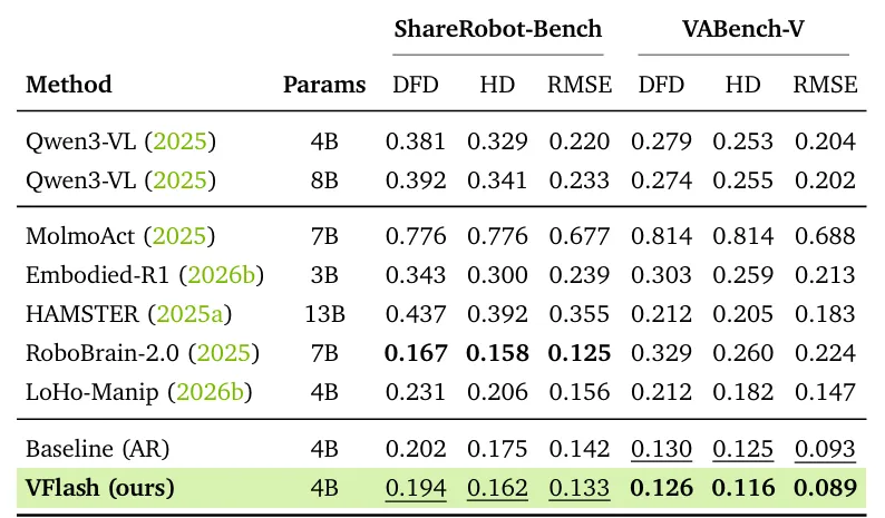
Table 2: Prediction of the opening circle 2D trajectoryDFD、HD and RMSE are both calculated under the Unified Image Coordinates, the lower the numerical value, the better. The reference method data comes from previous work; Baseline(AR) and VFlash use the same 4B target model, with only the decoder different.
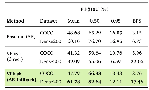
Table 3: Generate boundary frames with category conditions.The index is F1 (the higher the better) and the higher the number of BPS frames generated per second (the higher the better). Direct directly accepts the boundary frames that conform to each schema without verification; AR fallback reproduces the boundary frames that have not been checked with spatial confidence using band-bound AR decoding, see Appendix F.4. BPS is measured separately on each dataset.
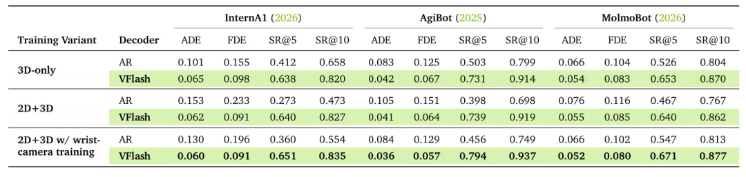
Table 4: Prediction of open-circle 3D robot trajectoryThe units of ADE and FDE are meters, and the lower the number, the better; SR@5 and SR@10 respectively, the higher the number, the higher the ratio of flight points within 5 cm and 10 cm respectively. The difference between the three variants is that the content of the model generated is only 3D or 2D+3D and that the wrist camera angle is included when training. All groups use the same single angle input to assess. The roughness represents the best value of each row.
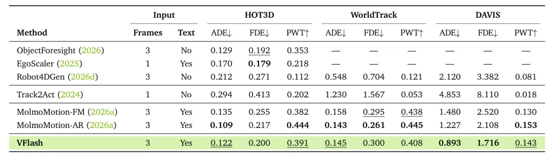
Table 5: 3D projections of the movement of points on PointMotionBench.VFlash uses MolmoMotion-AR as a target model. Compared to AR, VFlash's single-rollout output is about 25 times faster, see Annex F.3 for details. The lower the ADE/FDE unit is, the better; Frames and Text respectively represent the observed historical coefficients and whether language input is used.
2D trajectory prediction.On ShareRobot-Bench and VABench-V, VFlash reduced all six error indicators of its AR target model, as shown in Table 2. On both benchmarks, HD decreased by 7%, DFD and RMSE by 3% and 6% respectively.
On VABench-V, the best-performing model LoHo-Manip, VFlash's every error is reduced by about 40% compared to its predecessor; however, our AR target model is already better than the baseline listed in the table. On ShareRobot-Bench, VFlash's performance is second only to RoboBrain-2.0.
2D boundary frame prediction.On COCO and Dense 200, VFlash with AR fallback is equivalent to AR on average F1, while decoding speeds increase by 2.6 tons 2.8 times, as shown in Table 3. At IoU 0.50, VFlash's F1 is higher, particularly in object-dense Dense200 scenarios; but at IoU 0.95, F1 is lower. If no fallback is used, the average F1 on the Dense200 will fall by about 20 percentage points.
3D trajectory prediction.On InternA1, AgiBot, and MolmoBot, VFlash improved four indicators for all three target model variables, as shown in Table 4.
For 3D-only output target models, ADE decreased 18 per cent to 49 per cent; for 2D+3D output target models, ADE decreased 28 per cent to 61 per cent. On AgiBot, the flight point accuracy within the 5 cm threshold was increased from 50 per cent to 73 per cent and from 40 per cent to 74 per cent, respectively.
When combined with 2D+3D output, AR's 3D ADE is 15% and 51% higher than 3D output alone; while VFlash maintains a relatively close accuracy of predicting the two parts through a parallel forward propagation. Adding the wrist camera angle to the training allows VFlash's ADE to be further reduced by 3% and 12%; the evaluation still uses only the camera master.
3D motion predictions.On PointMotionBench, we froze the MolmoMotion-AR's spine model, taking the prediction of the query points in each future frame as a block, and using a fixed-width digital layout, see Appendix A.
As shown in Table 5, VFlash reduced ADE and FDE on DAVIS by 27% and 19% respectively, and FDE on HOT3D by 8% respectively. On HOT3D and WorldTrack, its ADE ranked second, behind AR, but superior to the Flow Matching variant. However, FDE on WorldTrack increased by 15% and PWT on the three datasets decreased by 7% and 12% respectively.
These results extend VFlash to density motion predictions using text tokenization coordinates: multiple error indicators are improved compared to AR, while single-rollout generation speeds are increased by about 25 times, see Appendix F.3.
3.2 Downstream applications
The experiment is set.We prefer to make controlled comparisons with the input of visual program conditions, rather than maximizing benchmark scores with additional model enhancements. In all configurations, VLM remains frozen; the action strategy is conditioned by its encoding of the generated program and the hidden state of the visual context.
MolmoSpaces。For MolmoSpaces, the strategy is a world action model (World Action Model, WAM) that was developed through robot-controlled post-training on Cosmos-Predict 2.5.
WAM reads the VLM in question, the subtasks generated, and the hidden state of a 2D+3D trajectory visual plan containing 10 flight points. After linear projection, these states are entered into the existing text-cross-attention path of WAM. WAM maintains its own camera and robot state input, predicts the Action Chunk length of 20 steps, and requests a new program after each of the three Action Chunk executions. The baseline is unmodified WAM, retaining its original text encoder.
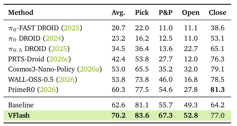
Table 6: Results from the MolmoSpaces operation.Baseline and VFlash use the same WAM; Baseline retains its original text encoder, and VFlash replaces it with our VLM and conditioned it on the program generated.
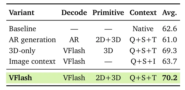
Table 7:All variants use the same WAM, but with different decoders, element types, or condition characteristics. Baseline uses WAM's original text encoders. Q,S,T, and I respectively represent problems, subtasks, trajectories, and the corresponding VLM hidden characteristics of image tokens.
As shown in Table 6, the average success rate increased from 62.6% to 70.2% on the basis of visual planning, averaging 9.9 percentage points higher than the public model PrimeR0 listed in the table, and scoring higher on three of the four tasks.
Compared to baselines, the biggest upgrades were Pick & Place and Close, which increased by 11.6 and 12.8 percentage points respectively; Pick increased by 2.5 percentage points. This suggests that the benefits of a visual program may be greater for tasks involving multiple interdependent actions.
Table 7 compares different projection representations and conditional input options. 2D+3D projects that use AR to replace VFlash projects have an average success rate of 61.0% from 70.2%. Using image status to replace trajectory status, the success rate has dropped 6.5 percentage points to 63.7%. Using 3D projects alone, the 2D+3D projects have achieved the highest average success rate.
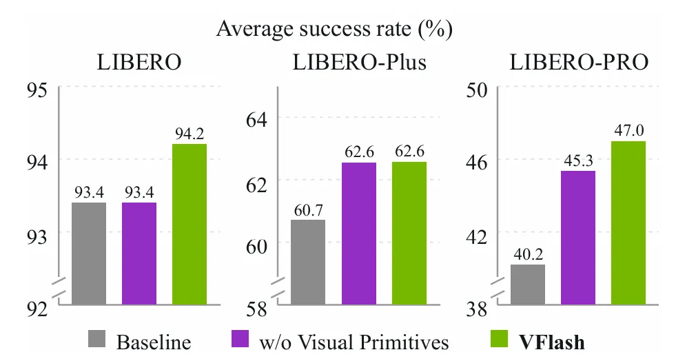
Figure 3: The LIBERO series benchmark.Comparing the average success rate of the same PIv3 head under different conditions: %: frozen Qwen3-VL-4B (Baseline); the status of the generated subtasks in our VLM (no visual graphs); and the complete visual program (VFlash).
The LIBERO series.At LIBERO, LIBERO-Plus and LIBERO-PRO, we trained a PIv3 Action Head based on Flow Matching in StarVLA and read frozen VLMs through cross-attention in each layer.
Given the main camera and wrist camera images, the VLM becomes a submission and a 2D+3D trajectory containing 10 flight points before each Action Chunk with 8 moves is generated. We compare the condition to the VLM state of the intercepted submission, and the condition to the fully programmed VLM state. The baseline uses the same Action Head, but the frozen Qwen3-VL-4B only encodes images and instructions.
As shown in Figure 3, the success rate increased from 0.8 percentage points on LIBERO to 1.9 percentage points on LIBERO-Plus and 6.8 percentage points on LIBERO-PRO compared to the baseline, indicating greater gains in the event of disruption.
On LIBERO-PRO, compared to baseline, the visual program improved Spatial, Object and Goal by 11.1, 9.4 and 6.9 percentage points respectively. Compared to submission-only conditions, the visual program improved Spatial by 2.6 percentage points, Goal by 1.2 percentage points, Long by 2.0 percentage points. This suggests that the trajectory provides useful information beyond the generated subtasks.
Table 8: Autonomous driving results from the NAVSIM and Waymo test kits.RL represents reinforcement learning; ↑ and ↓, respectively, represent the higher the better and the lower the better.
Autonomous driving.For NAVSIM and Waymo, the strategy is a Diffusion Transformer based on ReCogDrive. It reads the final state of the VLM in the prompt and generating plan through cross-attention, while reading from the vehicle's history and vehicle status, and outputting a continuous trajectory.
VLM stays frozen and generates a 2D+3D trajectory on each dataset's native grid. We train different heads on the Waymo, NAVSIM and Alpamayo derivatives respectively.
As shown in Table 8, VFlash uses a frozen planning VLM and a small Action Head to achieve competitive driving performance. After supervised training, it reached 87.1 PDMS on NAVSIM, up from 86.8 on ReCogDrive; 7.79 RFS on Waymo, equivalent to 7.78 on Qwen-Drive-1.0-SFT.
After RL for Action Head, the scores were upgraded to 90.7 PDMS and 7.86 RFS, respectively: on NAVSIM, it was level with Qwen-Drive-1.0-RL, and on Waymo, it was 0.05 RFS different from the best results in the table.
These results together suggest that VFlash is capable of supporting competitive, planned-conditioned driving performance while significantly reducing decoding delays, see section 3.3.
3.3 Analysis of throughput
Figure 4 divides the batch size on Jetson Thor, DGX Spark and H100 into four parts of the visual coding, prefill, decoding and action model.
Thor is an embedded platform for robots and vehicles, Spark is a desktop-level system, both of which are typical end-side hardware for System-1 visual planning described in Section 1; and H100 serves as a server-side reference.
On different devices, VFlash shortened the MolmoSpaces each step delay by 5.2 times on Thor and Spark, 3.6 times on H100; 3.4 times 3.6 and 2.6 times on NAVSIM respectively. On Waymo, as shown in Figure 5, the H100 each step delay was shortened by 4.5 times.
Almost all of the revenue comes from the decoding phase: on Thor, AR decoding accounts for 75% to 87% of the total time per step; VFlash shortened this part of the time by 12 to 42 times, while the rest remained the same.
For every token generated, AR decoding requires a 4B VLM forward propagation: on Thor it is 35×39 ms, on Spark it is 33×40 ms, on H100 it is 4.7×6.0 ms. Therefore, the decoding time and the number of tokens increases almost linearly.
Draft generation predicts the remaining token in a token containing 36 to 84 tokens, 13 to 23 ms on Thor and 1 to 3 ms on H100. Verification still needs to be spread forward for each block to run a target model, so its yield depends on the number of tokens actually submitted per round.
Figure four:VFlash will split the delays into pre-processing with ViT, prefill, decoding and WAM/DiT.
On MolmoSpaces, DFlash submits 5.5 tokens per round when processing submission text; however, within the trajectory block, only 2.2 tokens per round are submitted: even if the geometric error is small, it cannot be verified by formula 2 as long as the quantized distance between a coordinate and the target model is one bin. Thus, DFlash can only reduce decoding time by about half.
VFlash skips the token-level verification of the visual graph, with each graph using only one draft model to propagate and one target model to propagate. The forward propagation of the target model is used to update the cache and extract the hidden state for Action Head; its expenses are distributed throughout the block.
On Thor, when the driving token is increased from 36 tokens to 84 tokens, the decoding time is 72 to 78 ms. Therefore, in this range, more intensive plans will only add little delay.
4. Related work
VLM and visual programming.Physical VLMs are increasingly being used as high-level modules that convert visual observations and language instructions into plans, availability and trajectories. Space prediction is at the core of these models: points and boundary frames are used to position objects or availability, and trajectories describe expected or predicted movements.
These visual plans can be input as a condition of the operating strategy, or as a prompt feedback to the model. Other work involves spatial reasoning prior to the operation, predicting future states, or planning driving trajectories based on scenarios.
These studies focused on what a physical model should predict, and we focused on how quickly such spatial predictions could be generated. Coordinate generation per token meant that every time a flight point, object, or dimension was added, a decoding step was added.
Parallel decoding and guess decoding.Predicting decoding by simultaneously validating multiple draft tokens to accelerate LLM reasoning. Medusa, EAGLE, TIDAR, and DFlash explore different ways to generate these drafts.
For visual output, LocateAnything decodes as units of points and boundary frames, but is limited to fixed-sized 2D graphics. Spec-VLA is closest to this work: it speeds up OpenVLA by executing draft tokens that come close to the target model by accepting the quantized range. However, it still needs to validate each token for the target model and submit only 2.10 and 2.94 tokens each time forward propagation occurs.
Our finding is that, for visual trajectory prediction, a draft that is transmitted forward is more accurate than a return-to-target model. Based on this finding, VFlash generates the entire visual element in a forward-to-target transmission without relying on consistency with the target model.
The body model and the System-1 model.In the closed loop of sensory feedback actions after deployment, the delay of VLM directly limits the response speed of the intelligent body. Previous efficiency studies mainly accelerated action execution pipelines, such as using action compression, parallel Action Chunk or Flow Matching. However, previous VLM-based scheduling typically still relied on highly automated token decoding.
System-1 models such as Jev are able to quickly make band-type decisions for direct downstream applications; Visual Jev answers multiple interdependent visual questions in parallel after an image is encoded. Our work can be seen as a related exploration that enables VLM to make System-1 space predictions.
In this context, we have studied optimized token expression and decoding systems, while supporting special special tokens and ordinary numbers.
In summary, VFlash uses DFlash-style drafting, but does not require token alignment with the target model. It generates the fast, accurate visual programming implemented by LocateAnything's parallel boundary frame decoding, and expands to more rich, more general and useful visual graphics elements for downloadable hardware. Through system research, VFlash has also achieved more efficient decoding parallelism.
5. Conclusions
We came up with VFlash, which uses a known structure of visual graphs to predict alternate sequence coordinate generation in parallel.
Experimental results suggest that useful spatial predictions do not necessarily need to replicate the output of the regression model: directly generated drafts reduce robot trajectory errors; timing estimates for single rollouts show that the 3D object point predictions are generated about 25 times faster than planned conditional operation tasks further demonstrate how these predictions support downstream motion generation.
Future work will explore whether, under a fixed delay budget, the generation of multiple complementary parameters based on shared observations can improve control performance.